DS18B20 Temperature Sensors ESP32, MQTT and WiFi - HowTo
In addition to connecting a flow meter via RS485 I plugged 5-piece DS18B20 temperature sensors to the ESP32 so that their values are also transmitted to HomeAssistant via MQTT.
Connecting temperature sensors
When connecting multiple DS18B20s, they can be easily connected in parallel:

Yellow (Orange): Pin 14
Red: 3.3V
Black (Brown): GND
Between the data pin (orange) and 3.3V (red) a 4.7K Ohm resistor is inserted.

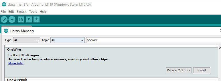
Library Manager
As a prerequisite for reading DS18B20 temperature sensors, the following libraries are required: OneWire and DallasTemperature


Reading the temperature: First Sketch - ByIndex
For a first try, I simply read out the temperatures of the sensors, at first only by index:
#include
#include

const int SensorDataPin = 14;

OneWire oneWire(SensorDataPin);

DallasTemperature sensors(&oneWire);

void setup() {

  Serial.begin(115200);
  sensors.begin();
}

void loop() {
  sensors.requestTemperatures();
  Serial.print("S0: ");
  Serial.print(sensors.getTempCByIndex(0));
  Serial.println(" ºC");
  Serial.print("S1: ");
  Serial.print(sensors.getTempCByIndex(1));
  Serial.println(" ºC");
  Serial.print("S2: ");
  Serial.print(sensors.getTempCByIndex(2));
  Serial.println(" ºC");
  Serial.print("S3: ");
  Serial.print(sensors.getTempCByIndex(3));
  Serial.println(" ºC");
  Serial.print("S4: ");
  Serial.print(sensors.getTempCByIndex(4));
  Serial.println(" ºC");
  delay(10000);
}
So that the numbering of the sensors does not change with an adjustment, the sensors can be called also over their address:
Find out address
If you want to read more than one temperature sensor, it is better to query the sensors by their address. The first thing we have to do is to find out the addresses of the individual sensors:
/*
 * Rui Santos
 * Complete Project Details https://randomnerdtutorials.com
 */

#include

// Based on the OneWire library example

OneWire ds(14);  //data wire connected to GPIO15

void setup(void) {
  Serial.begin(9600);
}

void loop(void) {
  byte i;
  byte addr[8];

  if (!ds.search(addr)) {
    Serial.println(" No more addresses.");
    Serial.println();
    ds.reset_search();
    delay(250);
    return;
  }
  Serial.print(" ROM =");
  for (i = 0; i < 8; i++) {
    Serial.write(' ');
    Serial.print(addr[i], HEX);
  }
}
see also: randomnerdtutorials.com/esp32-multiple-ds18b20-temperature-sensors/ and
When starting the sketch, the addresses of the sensors are output:
ROM = 28 FF 48 C8 89 16 3 F2 ROM = 28 FF 28 CE 89 16 3 EA ROM = 28 FF B2 CA 89 16 3 EE ROM = 28 FF CE 8F 92 16 4 CB ROM = 28 FF B C8 92 16 4 5D No more addresses.Inserted in a new sketch, the previous example can be extended:
#include
#include

const int SensorDataPin = 14;

OneWire oneWire(SensorDataPin);

DallasTemperature sensors(&oneWire);
DeviceAddress sensor1 = { 0x28, 0xFF, 0x48, 0xC8, 0x89, 0x16, 0x3, 0xF2 };
DeviceAddress sensor2 = { 0x28, 0xFF, 0x28, 0xCE, 0x89, 0x16, 0x3, 0xEA };
DeviceAddress sensor3 = { 0x28, 0xFF, 0xB2, 0xCA, 0x89, 0x16, 0x3, 0xEE };
DeviceAddress sensor4 = { 0x28, 0xFF, 0xCE, 0x8F, 0x92, 0x16, 0x4, 0xCB };
DeviceAddress sensor5 = { 0x28, 0xFF, 0xB, 0xC8, 0x92, 0x16, 0x4, 0x5D };


void setup() {

  Serial.begin(115200);
  sensors.begin();
}

void loop() {
  sensors.requestTemperatures();
  Serial.print("S1: ");
  Serial.print(sensors.getTempC(sensor1));
  Serial.println(" ºC");
  Serial.print("S2: ");
  Serial.print(sensors.getTempC(sensor2));
  Serial.println(" ºC");
  Serial.print("S3: ");
  Serial.print(sensors.getTempC(sensor3));
  Serial.println(" ºC");
  Serial.print("S4: ");
  Serial.print(sensors.getTempC(sensor4));
  Serial.println(" ºC");
  Serial.print("S5: ");
  Serial.print(sensors.getTempC(sensor5));
  Serial.println(" ºC");
  delay(10000);
}
At this point I started the sketch and touched the sensors in order to make them show a higher temperature and labeled them afterwards.
all together WiFi, MQTT, Flowmeter and DS18B20
Building on the project with WLAN and the flowmeter, I added the temperature sensors to the project as follows:
#include
#include
#include
#include
#include
#include

#define RX_PIN 17 // connect to converter's RX wire
#define TX_PIN 16 // connect to converter's TX wire
#define MODBUS_DEVICE_ID 1
#define FLOW_REGISTER 1
#define FLOW_DATA_SIZE 2
const int TEMP_PIN = 14; // connect to DS18B20
OneWire oneWire(TEMP_PIN);

SoftwareSerial swSerial(RX_PIN, TX_PIN);
ModbusMaster sensor;
DallasTemperature sensors(&oneWire);
DeviceAddress sensor1 = { 0x28, 0xFF, 0x48, 0xC8, 0x89, 0x16, 0x3, 0xF2 };
DeviceAddress sensor2 = { 0x28, 0xFF, 0x28, 0xCE, 0x89, 0x16, 0x3, 0xEA };
DeviceAddress sensor3 = { 0x28, 0xFF, 0xB2, 0xCA, 0x89, 0x16, 0x3, 0xEE };
DeviceAddress sensor4 = { 0x28, 0xFF, 0xCE, 0x8F, 0x92, 0x16, 0x4, 0xCB };
DeviceAddress sensor5 = { 0x28, 0xFF, 0xB, 0xC8, 0x92, 0x16, 0x4, 0x5D };

const char* ssid = "home";
const char* password = "???";
const char* mqttServer = "192.168.1.5";
const int mqttPort = 1883;
const char* mqttUser = "mqtt";
const char* mqttPassword = "???";

WiFiClient espClient;
PubSubClient client(espClient);

void setup() {
  Serial.begin(9600);
  WiFi.begin(ssid, password);

  while (WiFi.status() != WL_CONNECTED) {
    delay(5000);
    Serial.println("Connecting to WiFi..");
  }

  Serial.println("Connected to the WiFi network");

  swSerial.begin(9600);
  sensor.begin(MODBUS_DEVICE_ID, swSerial);

  client.setServer(mqttServer, mqttPort);

  while (!client.connected()) {
    Serial.println("Connecting to MQTT...");
    if (client.connect("ESP32Client", mqttUser, mqttPassword )) {
      Serial.println("connected");
    } else {
      Serial.print("failed with state ");
      Serial.print(client.state());
      delay(10000);
    }
  }
}

void loop() {
  client.loop();
  readFlow();
  readTemp();
  delay(3000);
  if (!client.connected()) {
    delay(60000);
    if (!client.connected()) {
      ESP.restart();
    }
  }
}

void readFlow() {
  uint8_t result;
  uint16_t buf[2];
  float flow;
  result = sensor.readHoldingRegisters(1, 2);
  if (result == sensor.ku8MBSuccess)
  {
    buf[1] = sensor.getResponseBuffer(0);
    buf[0] = sensor.getResponseBuffer(1);
    memcpy(&flow, &buf, sizeof(float));
    client.publish("flowmeter/flow",  String(flow).c_str());
  }
}


void readTemp() {
  sensors.requestTemperatures();
  float temp1 = sensors.getTempC(sensor1);
  if(temp1 != -127.00){
    client.publish("heating/t1",  String(temp1).c_str());
  }
  float temp2 = sensors.getTempC(sensor2);
  if(temp2 != -127.00){
    client.publish("heating/t2",  String(temp2).c_str());
  }
  float temp3 = sensors.getTempC(sensor3);
  if(temp3 != -127.00){
    client.publish("heating/t3",  String(temp3).c_str());
  }
  float temp4 = sensors.getTempC(sensor4);
  if(temp4 != -127.00){
    client.publish("heating/t4",  String(temp4).c_str());
  }
  float temp5 = sensors.getTempC(sensor5);
  if(temp5 != -127.00){
    client.publish("heating/t5",  String(temp5).c_str());
  }
}
see also
- ESP32 Flowmeter - RS485 Modbus
- ESP32 MQTT - Send data
- WiFi Example
For an ESP-Home version of this project, see: DS18B20- Temperature sensors in ESP-Home
 ({{pro_count}})
{{percentage}} % positive
 ({{con_count}})
THANK YOU for your review!
Top articles in this section
As described on the article ESP32 programming, Arduino - install requirements, my first goal was to read out a TUF-2000M Ultrasonic Flow Meter via an ESP32. I found an example for an ESP8266 on the internet: Reading a TUF-2000M Ultrasonic Flow Meter with an Arduino or ESP8266 and https://forum.arduino.cc/t/comunicacion-rs485/698786/2. I described the setup of the TUF-2000M in the following article: Field Report: Ultrasonic Flow Meter TUF-2000M. To be able to read out the TUF-2000M via RS485, it...
Complementary to the article: DS18B20 Temperature Sensors ESP32, MQTT and WiFi - HowTo, I have meanwhile replaced the Arduino project with ESP-Home. Simple projects can be implemented much easier in ESPHome. As an example, in ESPHome these 2 lines are enough to address the temperature sensors:

With ESPHome it is very easy to program your own microcontroller for use in HomeAssistant. My first use for a self-programmed microcontroller was to record the water flow and temperature values of my heater, see: ESP32 programming, Arduino - install requirements.